Calibration of my chrono-tacho
This covers the calibration only. It has been too long since (and too
many late nights during) the conversion to try to
chronicle it now.
This is for those without access to a quality function generator, but enough
technical know-how to understand what I'm
saying here. To put it another
way, if you are having trouble following along, get somebody else to do it for
you! ;-)
| |
 |
|
 |
|
|
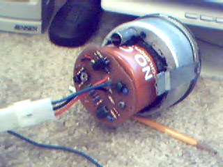
Totally re-worked. Can't tell,
huh? ...except there's no hour hand. I was going to use it as a
redline needle, but just getting it in there was turning into a huge
pain!
One of these days I'll take the rings back off and restore them to
their original condition. But not today.
|
|
Not too bad. MANY hours. I used
the cap to the conformal coating spray can as a housing and PCB
mount. It says 'NO CFC's.' Also, there is a tiny drain hole
on the underside just in case. If I recall, the clock housing had
one.
Oh, I didn't build the PCB. It and the movement are the guts
from a $50 FLAPS tach. I did, however, remove and hardwire the cyl
switch to 4cyl, remove the backlighting components, RTV the capacitors
to the board, shape it to fit and apply about ten coats of
conformal coating. Hopefully that will be enough! |
The files:
cal-tach-6-3.wav (3446 KB)
This is the original wav file for calibration
cal-tach-6-3.mp3 (626
KB) Smallest size file that gives 'good enough'
results (For the bandwidth-challenged)
cal-tach.divx.avi (846 KB) My neato
clock-tach conversion in action, and a good reference for your
calibration.
You'll need the Divx 5.0.2 codec, available here. The original capture was 41 MB!
The Instructions:
First of all, use these At Your Own Risk. This
worked for me, but I cannot be responsible if it doesn't
work for you or if you
short out your power supply or blow up your tach.
What's Needed:
- Powered speakers with a headphone jack. (Most sound cards
just don't have enough ass.)
- 1/8" stereo patch cable
- Grounded 12V power source. I use an available
connector in my computer. +12V is the yellow one.
> A twelve volt wall
adapter will work, but I don't like the way you have to set it up.
- A whole bunch of wire and connectors, and most importantly,
patience. This is worth it, remember?
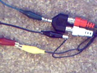 |
Red gator
- tach 12V
Black gator - tach ground
Green gator - tach signal input
Yellow gator - computer 12V
The Black gator is connected to
both the computer 12V Return and the RCA shield - carefully snugged in
the connector.
The Green gator is connected only
to the Tip. It wouldn't hurt for it to be connected to the Ring
(middle section) also, but mine wouldn't stay on both very well. |
Best practices:
- Plug the patch cable into the speaker and connect the Tach
Signal Lead to the Tip of the Patch Cable.
- Connect the Black and Red tach wires to the Black and Yellow
power
connector leads in your computer.
> Okay, so you're not
going to open it up, right? Go ahead
and use the wall adapter, but now,
the Adapter Neg(-)
lead must also be connected to the Patch Cable Shield.
(There has
to be an audio return path to the amp.)
- Do your best to shut down any program that makes noise. My
tach especially hates the system default ding.
- Turn the volume on your speakers and the audio control
panel
up until your tach responds smoothly. Keep in mind
that the first ramp starts at 1 Hz and ends at 33 Hz, so even
the best sound cards
will have trouble producing this range.
We are not concerned with rpm below about 800 (26 Hz)
anyway, right?
- Play the cal-tach-6-3 file which I have painstakingly created. ;-p
Your tach should go from 0 to 6000 rpm, 1000 at a
time,
with 3 second transition and hold times and then a
~5 sec
return to 0.
If your player has an EQ, minimize
frequencies
above ~300 Hz to reduce distortion.
Adjustments:
- Generally there is a potentiometer on the control board that
affects accuracy. For linearity, most coil spring meter
movements are adjustable
by twisting and are usually sealed at the factory. You can get around
this,
but chances are you
don't need to.
Born-on-Date
10 Sep 2002 |
Site Updated
16 Jul 2003 |
Home
Email Me |